Friday, June 15, 2012

An Inductor And Different Types

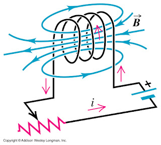
Inductance   is a   property  in an electronic circuit where a change in current in  a   circuit   creates a voltage in the  circuit itself and also the  nearby   circuits.  A  steady stream of  current in a conductor creates  a   magnetic field  around  the conductor. A  varying magnetic field  in  a   circuit  induces a  voltage in an adjacent conductor. An inductor is    a  passive electrical  component that stores energy in its magnetic     field.  Inductance is  created from the magnetic field that is formed    around a  conductor which  carries current that tends to oppose the change in current.

 Photo credit: softwareforeducation.com

Inductor Property
All conductors have inductance and can be made  into an inductor. A   length   of conductor can become an inductor and the  inductance will   be  greater  when it is wound into a coil. An inductor is  usually a    conductor turned  into a coil form, which concentrates or  increases   the  magnetic field  of the conductor.   An  electric current   through a inductor creates a magnetic flux or    magnetic field. A change  in the electric current also creates a    change  in the magnetic flux  which is proportional to the current.

Self Inductance
A     conductor has self inductance where a  change in the electric   current    through a circuit having inductance induces a proportional    voltage  that  opposes the change in  current. A varying magnetic field   in the  coil is  needed for inducing an opposing voltage  in the coil.   The  changing magnetic flux  generates an electromotive  force that   opposes  the change in current. This changing magnetic flux  induces a   voltage in  the coil. This voltage tend to oppose the change  and will    try to  decrease the current if it is increasing or increase  the   current  if it  is decreasing. This opposing flow of electric current is termed  as  self induction. Self inductance can be illustrated using an experiment. Here a battery is connected through a switch across a coil wound many times on an iron     core. A small lamp that lights on battery voltage is connected  across    the terminals of the  coil. An ammeter is connected in series to     the coil and the switch. When the switch is opened, the ammeter    reading  falls to zero but the lamp flashes very brightly and goes out.

 Photo credit: electronicsbasics1.blogspot.com

Mutual Inductance
Mutual     inductance happen when the coils are kept near so that the magnetic     flux from one inductor cross to the other and thus they exhibit  mutual    inductance. It is the phenomenon of production of induced  current in   one  coil by changing the magnetic flux due to current in  another coil.    The varying current in  the coil or circuit induces a voltage in an    adjacent coil or circuit  is called as mutual inductance. Mutual    inductance between coils  depends upon their coefficient of coupling,    which can vary from 0 to  1.

Factors Affecting Inductance
The inductance of an inductor depends on
1. The number of loops of the coil. The larger the number of turns the greater is the inductance.
2. The size of each loop. The greater the size of the loop, the greater is the inductance.
3. The permeability of the material used as the former to wind the  coil. The magnetic flux can be increased by coiling the conductor  around a    material with high permeability. Materials with high  permeability    includes soft iron, ferrite, etc.
4. Cross section of the core. The larger the cross section of the core, the higher the inductance.
5. Spacing of the turns. The smaller the spacing between the turns of the coil the greater is the inductance.

 Photo credit: hyperphysics.phy-astr.gsu.edu

The unit of measurement of inductance is the henry and the symbol for inductance is L 
An inductor of 1 henry of inductance produces an EMF of 1 volt when the current through the inductor changes at the rate of 1 ampere per second. Henry is a large unit and smaller units are usually used in    practice  especially in radio, where millihendry mH or microhenry microH are used.

The relationship between self inductance L, voltage, and current in a circuit is

V = L * di/dt

Where     V is the voltage in volts, L is the self inductance, i is the  current    in amperes,  and t is the time.  The voltage across the  inductor is    proportional to the product of its inductance and the  time rate of    change of the current through it.

Inductance     is present in almost all circuits which may have beneficial or     detrimental effects to the function of the circuit.  Inductors can be     used where the current and voltage changes with time. Inductors have    the  ability to  delay and shape alternating currents. Common   inductors   consists of a specific number of turns of enamelled copper wire, wound around  a  former such as air, iron, laminated steel, ferrite, Teflon etc.

Photo credit: electrocircuitschema.blogspot.com

An   ideal inductance has inductance but no resistance or capacitance and   does not dissipate or radiate energy. However real inductance have     resistances due to the resistance of the wire and the parasitic     capacitances due to electric field between the turns of the coil    having slightly different potentials. Energy is dissipated by the    resistance of the wire and by the losses of the magnetic core due to    hysteresis. 

Uses and Effects of Inductance
Inductances   are widely used in radio circuits, other analog circuits, and signal   processing. Inductances provide frequency selection in a tuned circuit   of the radio. Large inductors are used in power supplies to filter out   mains hum, power supply noises, and   fluctuations in the DC. Inductors are used in  filter  circuits  to   filter out waveforms or in energy storage systems. Audio  chokes have   many turns of wire on iron core, which has inductances of 1  to 100  henrys.   Radio frequency chokes  have inductances of a few turns of  wire wound  on  a nonmagnetic core. Power transformers are used in power  supplies  for most electronic equipments. Coupled magnetic fluxes  between a  stationary and a rotating inductor coil is used to   produce mechanical torque in induction motors. Inductors are used as  an  energy storage device in switch-mode power supplies. Variable  inductors  use an adjustable core, which is  usually a ferrite  core or  powdered  iron core, that can change the  inductance.

Inductances    are found in transmission cables that   determine the characteristic    impedance in a cable. Inductances are  also  seen in microphone and    computer network cables that use special  cables  to reduce it. Long    power transmission lines also shows  inductances which  limits the AC    power that can be sent through them.


Photo credit: emailschool.com

Types of Inductances
There are 2 types of inductors, fixed inductor and the variable inductor.

Fixed   inductors are air core inductor, radio frequency inductor,   ferromagnetic core inductor, laminated core inductor, ferrite-core   inductor, and toroidal core inductor.

Variable   inductors are  widely used in radio applications to set a definite   oscillating frequency and to tune the resonant circuits. These may   include many different types of slug tuned inductors. Slug tuned   inductors are widely used in RF and IF stages of super heterodyne radio receivers. Tuned inductors are also used as the tank coil in the final RF power amplifiers.


Tuesday, June 12, 2012

A Capacitor And Different Types

A capacitor is a passive component, which stores electrical charge or  electrical energy. Capacitors are more commonly used components in  an   electronic circuit. it is used for storing electrical energy. Capacitors vary by their voltage, dielectric material, capacitance, tolerance etc.

 Photo credit: g3npf.co.uk

Structure of a Capacitor
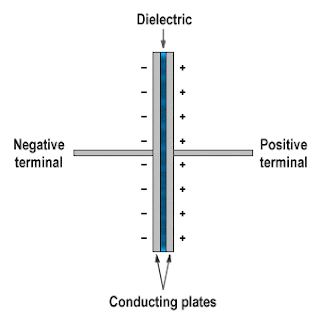
The  capacitor consists of parallel conductive plates that do not touch each  other and are separated by a dielectric material. It has two terminals,  which are connected to the parallel  conductive plates inside the  capacitor. The conductive plates of the capacitors are separated with an  insulating material, which is called the dielectric medium. The  conductors of the capacitor come in various shapes and sizes depending  on the  voltage and the amount of charge it stores. Dielectric of the  capacitor also varies depending on the voltage, capacitance, and  frequency of operation. Examples of dielectric media are glass,  air, paper, vacuum, metal oxide, polystyrene film, polyester film,  mica, semiconductor etc. The conductors and the dielectric medium is  enclosed in the body of the capacitor.
 

 Photo credit: engineersgarage.com

Capacitance  is the ratio of electric charge stored on each conductor to the  potential difference between them. The capacitance of a capacitor  depends on the surface area of the conductors, the distance between each  plates of the capacitor, and the dielectric constant of the material. The greater is the capacitance when  there is greater area of the conductors, closer distance between the  plates of the capacitor, and greater the dielectric constant. The capacitance is measured in Farad, which has the symbol (F). One  Farad is the capacitance when 1 coulomb of electrical charge is stored  in the conductor on the application of 1 volt of potential difference.

The charge stored by the capacitor is denoted by

Q = CV

Where,  Q is the charge stored by the capacitor, C is the capacitance value of  the capacitor, and V is the voltage applied across the capacitor.

Normal value of  capacitance is smaller and it is measured in microfarad, nanofarad,  and picofarad. A 3-digit code is used to indicate the value of the  capacitor. The capacitance value is written in letters and numbers and   also just in numbers according to the manufacturers description.  Capacitors are also characterized by the voltage  specification. The maximum voltage is the voltage  that can be applied  to a capacitor without breaking down the capacitor.  It is usually  written on the capacitor along with the capacitor value.

Photo credit: engineersgarage.com

Operation of a Capacitor
A   capacitor is isolated when there is no electrical charge across the   conductors. In an isolated capacitor, the conductors hold equal and   opposite charges on the conductor surface. When a DC voltage is applied   to the terminals of a capacitor, the capacitor gets  charged. The current begins to flow across the terminals and an  electrostatic charge develops across the conductive  plates  of the  capacitor. Energy as electrons are stored in the electrostatic field  across  the plates. The positive charge gets collected to one  plate and  the negative charge to the other. As the charges get accumulated on the  plates there is current flowing through  the terminals into the capacitor. The capacitor continues to charge  until its voltage equalizes with the voltage that is applied.  When the  capacitor is fully charged, the current flow is reduced and becomes  zero.  The capacitor is discharged gradually  over time when the voltage source is removed. It can also be discharged  when the terminals are made to contact with each other. When a higher charge is stored in the capacitor, it can give a spark while it is discharged.

 Photo credit: technologyuk.net

The breakdown voltage is the voltage that can be given to a capacitor  which  when exceeded will cause the dielectric to breakdown and become  a  conductor. The dielectric breaks down and becomes a conductor causing  a  large current to flow through the capacitor. It depends on the  capacitor  and the voltage specification that is being used. The failure  can be a  with an explosion with the capacitor exploding and spreading  the  contents around. When selecting a capacitor for use, the breakdown voltage rating must be twice or thrice the value of the operating voltage. Some capacitors such as the electrolytic capacitors show polarity that has +ive and -ive terminals. When connecting these capacitors the polarity needs to be correct, otherwise the capacitor might get damaged.

Capacitor Applications
Capacitors provide very large resistance to DC and small resistance for AC. Capacitors are used for a variety of applications such as blocking DC and bypassing AC currents, store charge in a flash camera, filtering the  power supplies from ripples and spikes, resonant tuned circuits and frequency  tuning in radios, coupling of stages, tone control in audio circuit,  timing circuits, phase alteration, stabilizing voltage and power flows  etc. Applications such as storing very high charges as required in a  battery are being gradually developed.

 Photo credit: technologyuk.net

Types of Capacitors
There are many different types of capacitors, based on the type of conductive electrodes and the dielectric used in making them. There are 2 major types of capacitors, fixed capacitors and variable capacitors.

1. Fixed capacitors
A. Film capacitors such as paper capacitor, metalized paper capacitor, glass capacitor,  mica capacitor, silver mica capacitor, ceramic capacitor, polyester capacitor, polystyrene capacitor, metalized polyester capacitor, polycarbonate capacitor, polypropylene capacitor, Teflon capacitor, porcelain capacitor, etc.
B. Electrolytic capacitors such as aluminum electrolyte capacitor, tantalum electrolyte capacitor, etc.

2. Variable capacitors
The variable capacitors include air variable capacitor, polyester film capacitor, etc.

Electrolytic Capacitors
The  electrolytic capacitors have a positive and a  negative electrode.  Aluminum  is used as the electrode in an electrolytic capacitor. A thin  oxide  layer act as the dielectric material in this capacitor. These  capacitors  can vary in capacitance from 1 micro Farad to thousands of  micro  Farads. It is used in varying DC voltage   conditions for power supply applications. Electrolytic capacitors are   used  as ripple filters in power supply units and also as a  filter for   bypassing low frequency signals in audio amplifiers etc. There is   polarity written on an electrolytic capacitor either + or - sign, which   indicates the terminals when connecting to the voltage.   Reversing the terminals of the electrolytic capacitor can cause damage   to the capacitor and also sometimes the capacitor may explode with  some  gases and the contents inside.

Tantalum Capacitors
Tantalum   capacitors are electrolytic capacitors and they use tantalum as the   electrode plates. They are superior than the aluminum electrolytic   capacitors in temperature and in frequency. They have high stability  and  are used in circuits which demand high stability in capacitance  values.  They are used in analog signal  circuits. It is a little bit more  expensive than the electrolytic  capacitors. Tantalum capacitors comes in  values such as 0.33  micro Farads, 0.47 micro Farads, 10 micro Farads etc.

Ceramic Capacitors
Ceramic capacitors are made of materials such as titanium and barium oxide used as the dielectric. They are usually seen as disc shaped. The  capacitance values are considerably smaller. They have no polarity.  They  are suitable for high frequencies. They are mostly used to bypass high frequency signals to the ground in circuits. Usual values of ceramic capacitors are 10 pico Farad, 100 pico Farad, 0.01 micro Farad, etc.

Polystyrene Film Capacitors
These  capacitors have the polystyrene film as the dielectric. Copper is used  as the electrode  material They are used in filter circuits, and in  timing circuits. 

Electric Double Layer Capacitors
These   capacitors are also called as super capacitors. Super capacitors store large capacitance and have values in farads, which is a large value of capacitance. They have values such as 0.47 Farad.

Polyester Film Capacitors
These   capacitors use polyester film as the dielectric material. They do not   have high tolerance level and have reasonable tolerance of +/-5 to   +/-10. They are very cheap. They comes in values ranging from 0.001  micro Farads, 0.1 micro Farads, 0.22 micro Farads etc.

Polypropylene Capacitors
Polypropylene film is used as the dielectric. These capacitors are used where higher tolerance is necessary.

Mica Capacitors
These capacitors use Mica for the dielectric. Mica capacitors have good stability as their temperature coefficient is small. They have good insulation. They have high frequency tolerance and so they are used in resonant tuned circuits and high frequency filters etc. They also have  high voltage tolerance. Usual values for Mica capacitors are 47 pico Farads, 220 pico Farads, 1000 pico Farads, etc.

Metallized Polyester Film Capacitors
These are a type of polyester film capacitor. Their electrodes are thin and so they are small in size. They are rugged and they have no polarity.

 Photo credit: electronics-made-easy.com

Variable Capacitors
Tuning Capacitors
This is a large variable capacitor used for tuning the radio. It is also called as a gang condenser. It consists  of  2 sets of plates, which can be varied by a spindle or a tuning  control.  There may be rotation control, spindle, or screws that helps to vary the capacitance. Air or polyester film is used as the dielectric. When an air is used as a dielectric usual values that can be varied is 5 pico Farads to 40 pico Farads and in polyester film capacitor, 12 pico Farad to 150 pico Farad can be varied.

Trimmer Capacitors
These are capacitors, which can vary their capacitance values. The value of the capacitance is varied by the use of a control. They have moving plates fixed one above the other in sets. One set of plates can be moved while the other set may be fixed to the frame. The movable plates are rotated to vary the capacitance range. The capacitor is varied by turning a screw. Mostly air or polyester film is used as the dielectric. They are used in fine tuning and adjusting the resonant circuits in a radio.


Sunday, June 10, 2012

A Resistor And Different Types

A resistor is a two-terminal passive electronic component used in an electronic circuit that have a stated value of resistance. It is used to implement an electrical resistance in an electronic circuit. For the current to flow through a resistor, a potential difference is required between the two terminals of the resistor.

Photo credit: amateur-radio-wiki.net 

The current through a resistor is proportional to the voltage across the resistance terminals. This relation is represented by the Ohm's law.

I = V/R

where I is the current through the terminals of the resistor, V is the voltage, and R is the resistance of the resistor. It can be also be cross multiplied to get the other values when 2 of the values are known. The unit of resistance is ohms. When the current flows through the resistor there will be resistance to the flow of current and as a result heat is dissipated from it.
There are a range of commercially manufactured resistors available in the market. The resistors comes with different resistance values as well as power or wattage rating. The electrical resistance value of the resistor is marked on it. The tolerance of the resistor along with the temperature coefficient is also written on it. Resistances of higher power rating are usually larger and bulky in size.
Resistances have characteristics such as series inductance and parallel capacitance, which may affect its performance in higher frequencies. The noise characteristics in the resistors is important in low noise electronic circuits such as RF amplifiers or preamplifier stages. The temperature coefficient of the resistance interfere with the resistance and the tolerance rate of the resistor.


Photo credit: encyclopedia2.thefreedictionary.com

Types of Resistors
There are different types of resistors that are available in the market for using in electronic circuits. These resistors differ in the properties depending upon their manufacture and construction. Resistors are used in different applications with the frequency characteristics ranging from audio range of frequencies to ultra high frequencies.

Resistors are broadly classified into:

Fixed Resistors
These are the most commonly used resistors in electronic circuits. The value of the fixed resistor is a fixed one and cannot be changed in general. Their resistance is predetermined during the time of the manufacture and are available with a fixed value. The resistance values of the fixed resistors are marked using a color code, which is displayed as colored bars or colored stripes. The color coding for the resistors are used because the size of the resistor is very small for the resistance value to be written on it. The value of the resistor is a discrete value that is distinct from other values. There are 4 to 6 bands of colors marked on it for denoting its resistance values. The last band denotes the tolerance of the resistor which is the amount of the fixed value of the resistor that can vary during its use. The tolerance is calculated as a percentage value. Resistor values such as 1, 2.2, 4.7, 5.6, 10 etc. are usually seen. The different types of fixed value resistors are carbon film resistors, metal film resistors, and wire wound resistors.

Photo credit: learnabout-electronics.org 

Variable resistors
This is a resistor where the resistance of the resistor can be varied by changing the slider of the resistor. This consists of a main fixed resistor element and a slider, which taps on to the resistor. The value of the resistor can be varied to a suitable value by moving the slider control during the use. The slider control can be varied with the slider tap moving along the entire length of the resistor element. This consists of 3 connections, two of them are connected to both ends of the resistor element and one to the slider component. The connection can be taken between all these three connection positions or any one end of the resistor element and the slider. The rotation angle of a variable resistor is usually around 300 degrees. 
 
Photo credit: circuitstoday.com

There are 3 general types of variable resistors that are used.
1. Variable control resistor: The value of the resistor is changed or controlled during the operation of a circuit. Eg. Volume control of a radio. When the control is moved or turned around, the value of the resistor is changed and the volume or whatever is adjusted.
2. Semifixed resistors: The value of the resistor is changed by a slider and fixed to that position for the best performance of the circuit. Semifixed resistors are used to compensate for the inaccuracies of the resistor. It is also used to fine tune the performance of the circuit. These are also called as preset resistors. The value of the resistor is not meant to be adjusted by the user but instead by a technician. It is used to adjust the operating condition of the circuit by the technician.
3. Potentiometers: The value of these resistors are varied by turning the control of the resistor many times to use the whole range of the resistor. This allows for very precise adjustment of the resistor value. These are also called as multiturn potentiometers, trimmer potentiometers, or trimpots. Eg. Resistor tuning in a radio circuit or fine adjustments in a circuit.


Sunday, June 3, 2012

Active And Passive Electronic Devices

An electronic component forms a basic electronic element, which is available in a discrete form that has two or more electrical terminals. Electronic circuits are composed of many electronic components with different characteristics. These components are necessary for the circuit to perform the required function or purpose. The terminals of the electronic elements or components are connected together in a circuit board to create an electronic circuit that gives a definite function. An electronic component or device can be classified into passive or an active component.

Electronic Components
Photo credit: ​made-in-china.com 

Active Device
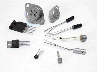
An active component device is one, which can supply energy into a circuit. It can strengthen a signal applied to it and shows gain such a current or voltage gain. These components are capable of controlling the current or flow of electrons in the device by means of another electrical signal applied to it. The energy is derived from the current or electrons flowing through the device by the application of another electrical signal. These components need power to improve the signal level and the source of power is usually obtained from the DC supply connected to the circuit. They also exhibit directional characteristics in the signal. These components can amplify the signal or increase power of the output electrical signal. Active components include components such as triode vacuum tubes, transistors, tunnel diodes, etc.

Thermionic Valves
Photo credit: 123rf.com


Transistors
Photo credit: mgitecetech.wordpress.com

Integrated Circuits
Photo credit: indiamart.com

Active devices can be either current controlled or voltage controlled. When another voltage is used to control the the current flow through the device, it is called as voltage controlled, and if it is controlled by another current, it is called as current controlled device.

Passive Device
A passive component or device, is one which cannot control the flow of current in the device. It cannot rely on an outside electrical source. It cannot supply energy into the connected circuit. They do not have gain and is not able to amplify a signal that is introduced to it. It allows a signal to pass through it and may often alter the impedance of the out coming signal. Sometimes it can be lossy and there is a net loss of signal power in a passive device. It may attenuate a signal, voltage, or current when it passes through them. Passive devices do not exhibit directional qualities to the signal. Depending on the device they can sometimes increase the current or voltage of the signal as seen in a transformer or a resonant circuit. Passive components include resistors, capacitors, diodes, inductors, transformers, cables etc.

Passive Components
Photo credit: tuttech.de

Passive components are further divided into lossless and lossy components. Lossless components do not have a net power flow through it, either into or out of it. Lossless components include capacitors, inductors, transformers etc. Lossy components will absorb the power when it passes through it. It dissipates power from the circuit and attenuates the signal. Lossy components include resistors. Most non ideal passive components are lossy in nature as it absorbs energy.