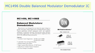
The MC1496 IC is a balanced modulator/demodulator IC used in various circuits for modulation or demodulation applications. It provides an output voltage, which is a product of an RF input from the antenna and a switching function through a carrier signal. This is a 14 pin IC, which is available as a dual inline or SOIC package.
The Important Features of MC1496 IC are
- It has excellent carrier suppression of typically -50dB at 10 MHz.
- Adjustable gain and signal handling characteristics.
- Balanced input and output circuits.
- High common mode rejection typically at -85 dB.
- This IC contains 8 active transistors.
Circuit Schematic of MC1496 IC
The inner circuit of the MC1496 IC consists of an upper quad differential amplifier driven by a standard differential amplifier with dual current sources. The output collectors are cross-coupled and therefore full-wave balanced multiplication of the two input voltages occurs. At the output, the collectors are terminated by two external load resistors or broadband transformers to the VCC.
The inner circuit of the MC1496 IC consists of an upper quad differential amplifier driven by a standard differential amplifier with dual current sources. The output collectors are cross-coupled and therefore full-wave balanced multiplication of the two input voltages occurs. At the output, the collectors are terminated by two external load resistors or broadband transformers to the VCC.
The output spectrum will contain only the sum and difference of the two input frequencies. The lower differential amplifier has the emitters connected to the external IC pins and therefore an external emitter resistance can be used.
MC1496 IC Operational Information
The upper quad differential amplifier may be operated in a linear or a saturated mode, whereas the lower differential amplifier is operated in a linear mode for most applications. The maximum input voltage for linear operation is approximately 25 mV peak with no emitter degeneration and the upper differential amplifier has its emitters internally connected. The lower differential amplifier has the facility for an external emitter resistance and its linear signal handling range may be adjusted by the user. This IC can be operated in a dual power supply as well as a 12V DC supply.
The basic application of the MC1496 IC is a balanced modulator with a double sideband suppressed carrier. This IC can also be used as a product detector, doubly balanced mixer, frequency doubler, phase detector and FM detector.
MC1496 IC Used as a Product Detector
The MC1496 IC can be used as an excellent product detector. It has a sensitivity of 3 uV and a dynamic range of 90 dB. The detector is broadband and responds well over the entire high frequency range.
MC1496 IC Used as a Product Detector
The MC1496 IC can be used as an excellent product detector. It has a sensitivity of 3 uV and a dynamic range of 90 dB. The detector is broadband and responds well over the entire high frequency range.
For operation at lower intermediate frequencies down to 50 kHz, the 0.1uF capacitors on pins 8 and 10 should be increased to 1 uF. The output filter at the 12th pin can be tailored to a specific intermediate frequency or audio amplifier input impedance.
MC1496 IC Circuit Description
The MC1496 IC product detector circuit is wired onto a PCB. The carrier input of around 300 mV RMS is given to the 10th pin of the IC. The RF signal from the antenna and RF amplifier is given to the 1st pin of the IC. The 14th pin is grounded. The 6th and 12th pins are given +12 volts VCC through a 3K resistor.
An output audio filter is given at the 12th pin through which the demodulated audio signal can be obtained. The emitter resistance between pins 2 and 3 may be increased or decreased to adjust the circuit gain, sensitivity and dynamic range of the product detector. This circuit may also be used as an AM detector when an AM signal is introduced at the RF input and a carrier signal at the carrier input.
Typical Applications of MC1496 IC are
Typical Applications of MC1496 IC are
- Carrier suppression.
- Amplitude modulation.
- Synchronous detection.
- FM detection.
- Phase detection.
- Chopper applications.


