Friday, September 24, 2021

What is an Envelope Detector | How to Construct a Diode Envelope Detector

An envelope detector is an electronic circuit that demodulates the envelope of an amplitude modulated information contained in an AM signal. It is a non-coherent type of linear AM detector. These are used in radio receivers to detect or demodulate the original audio signals that are present in an AM signal. It is also called as the peak detector.

There are many different types of envelope detectors. The simplest, cheap and widely used envelope detector is the diode envelope detector. In diode envelope detector, the linear property of the diode is utilized for detection. It produces an output signal that follows the envelope of an amplitude modulated waveform, which constitutes the original modulated audio signal. There are many other types of AM detectors that are built into integrated circuits in some advanced radio receivers.

Working of a Diode Envelope Detector
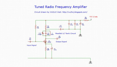
The diode envelope detector consists of a detector diode, wave-shaping components and a low pass filter. The diode is operated in the linear region of its characteristic curve. The capacitor C and resistor RL form the wave shaping components or timing components that selects the time constant. The RLC network that follows it provides the low pass filter. The signal from the output of the low pass filter is amplified using an audio amplifier that drives a loudspeaker.

The amplitude modulated RF signal is given at the input of the diode detector. During the positive half cycle, the diode becomes forward biased and acts as a closed switch. It allows the positive half cycle of the radio frequency wave to pass through. The capacitor C charges to the maximum of the positive cycle.

During the negative half cycle, the diode becomes reverse biased and acts as an open switch, which blocks the signal through the diode. During this cycle, the capacitor discharges through the load resistor RL until the next positive half cycle.

Thus a waveform is traced from the envelope of the detected AM signal by the action of the diode, capacitor and the load resistor. This signal may contain some portions of the RF signal, which can be filtered using a low pass filter.

RC Time Constant

During charging, the RC time constant must be short.
RC << (shorter than) 1/fc

During discharging, the RC time constant must be long.
RC >> (longer than) 1/fc

RC must also be << (shorter than) 1/fm, the maximum modulating frequency
Therefore 1/fc << RC << 1/fm

Where RC is the value of resistor and capacitor of the time constant
fc - carrier frequency
fm - maximum modulating frequency

Distortions in Diode Envelope Detector
1# Creation of spikes: Due to the charging and discharging of the capacitor, spikes are generated. To minimize the spikes, the RC values must be kept high.
2# Negative peak clipping: In signals that are over-modulated or signals with more than 100% modulation, the values on the negative side will be clipped. This can be minimized by selecting the proper RC time constant.
3# Diagonal clipping: This occurs at high modulation depth. When the RC time constant is too long, it cannot follow the changes in the envelope of the demodulated waveform. This distortion can also be reduced by selecting the proper time constant.
 
Advantages of Diode Envelope Detector
1# It is a very simple and most commonly used AM detector.
2# It is very cheap.
3# It is efficient.
4# It is very effective for detecting narrow band AM signals.

Applications of Diode Envelope Detector
1# It is commonly used for detecting amplitude modulated signals in radio and communication receivers.
2# It is used for detecting double side-band full carrier signals.
3# It is used in electronic circuits to detect the presence of RF signals and its measurement.

Watch the Video: https://youtu.be/OpdL3iqMD-4


What is a Multistage Tuned RF amplifier | How to Construct a Multistage Tuned RF amplifier

An amplifier that uses multiple stages of tuned RF amplifier for amplification of an RF signal is called a multi-stage tuned RF amplifier. The individual single tuned RF amplifier stages are connected together in series by a coupling device such as a capacitor or a transformer. The output of the first amplifier stage is coupled to the input of the second stage. This type of joining together of two or more amplifier stages is called as cascading.


Types of Multistage Tuned RF Amplifier
There are several types of multistage tuned RF amplifiers and they are
  1. Double tuned amplifiers: This is a transformer coupled amplifier. Here, both the primary as well as the secondary winding of the transformer is tuned. This type of amplifier has a wide bandwidth.
  2. Stagger tuned amplifier: This is a tuned amplifier where two or more single tuned amplifier stages are tuned to a slightly different frequency. This amplifier has a wider bandwidth and it overlaps each other. It has a moderate gain.
  3. Synchronous tuned amplifier: Here more than one single tuned amplifier is used and they are tuned to the same frequency. This amplifier has lower bandwidth and maximum gain.

Operation of a Multistage Tuned RF amplifier

The signal Vin that has to be amplified is given to the base of the first transistor Q1 through the capacitor C1. The transistor Q1 amplifies the signal and it is available at the primary winding of the transformer T1. The transformer T1 along with the parallel capacitor forms the LC tank circuit, which is tuned to the required frequency. The amplified signal from the collector is coupled to the input of the second transistor Q2 through the coupling capacitor C2.

The second stage provides further amplification of the signal and it is available at the primary winding of the transformer T2. The transformer T2 along with the parallel capacitor forms the LC tank circuit, which is tuned to the required frequency.


The amplified signal from the collector of transistor Q2 is available at the Vout through the coupling capacitor C3. The turns of the transformer can be adjusted so that the required coupling is maintained and thus maximum energy is transferred across the transformer windings.


The overall gain of a multistage tuned RF amplifier is determined by the formula

Gain of stage 1: Av1 = V2/V1

Gain of stage 2: Av2 = Vo/V2

Total gain of the stage is Av1 x Av2

Av = V2/V1 x Vo/V2 = Vo/V1
Av  = Vo/V1


Total gain of N number of amplifier stages is given by the formula
Av = Av1 x Av2 x AvN

Where Av = Overall gain
Av1 = Voltage gain of the 1st stage
Av2 = Voltage gain of the 2nd stage

Advantages of Multistage tuned RF amplifier

  1. The voltage gain of a tuned RF amplifier is very high.
  2. It has high impedance and high Q at its resonant frequency.
  3. It has adjustable bandwidth depending on the type of amplifier that is used.
  4. The current consumption of the amplifier is less.


Applications of Multistage Tuned RF amplifier

  1. It is used as a multi-stage RF amplifier in communication receivers.
  2. It is used as an IF amplifier in superheterodyne receivers.
  3. It is used as an IF amplifier in television receivers and communication equipment.
  4. It is used as an IF amplifier to convert higher frequency signals to a lower frequency in satellite receivers and communication equipment.

Watch the Video: https://youtu.be/HFm43ZZW5Hc


What is a Tuned RF Amplifier | How to Construct a Tuned RF Amplifier

A tuned RF amplifier is a type of radio frequency amplifier that selectively amplifies a narrow range of radio frequencies from a wide frequency spectrum. This amplifier employs a tuned LC tank circuit in the place of its load. This tuned circuit is capable of selecting a narrow band of desired frequencies while rejecting all others. This process of selecting a specific narrow range of frequencies from a broad frequency spectrum is called as tuning.

Working of a Tuned RF Amplifier
The resonant frequency of an LC circuit is the frequency at which the reactance of the inductor balances with the reactance of the capacitor. It is denoted by Fr.


A parallel tuned radio frequency amplifier offers high impedance at the resonant frequency, and does not allow much current through it. It offers low impedance to all other frequencies away from the resonant frequency.

The tuned radio frequency amplifier offers high impedance at resonance that allows signals at the desired frequency, but offers low impedance to frequencies above or below the resonant frequency, thus rejecting signals in those frequencies. Thus a tuned amplifier selectively amplifies the desired signals and rejects all other signals.

The formula for calculating the resonant frequency of the amplifier is

Fr = 1/2π√LC

The Q factor or the sharpness of the resonance curve of the LC tuned circuit of the amplifier determines the selectivity of that circuit. The Q factor of a resonant circuit is dependent on the internal resistance of the inductor (L) of the circuit. The lower the resistance of the inductor, the higher the Q factor.

 Tuned Radio Frequency Amplifier Circuit


Advantages of Tuned RF Amplifiers
1# The use of reactive components in a tuned radio frequency amplifier such as the inductor and the capacitor reduces the power loss at resonant frequency due to the high impedance which makes it efficient. Thus a smaller collector supply voltage is necessary.
2# The selectivity and amplification of the desired radio frequency signal is high in tuned radio frequency amplifiers.


Applications of a Tuned Radio Frequency amplifier

  1. A tuned RF amplifier is used as a front-end radio frequency amplifier in radio, television and communication receivers.
  2. It is used as a tuned Intermediate frequency amplifier in radio, TV and communication receivers.
  3. Tuned amplifier is used as a selective RF amplifier to amplify only the desired signals in transceivers and transmitters.
  4. RF power amplifiers utilize tuned RF amplifiers to amplify the required signals before they are being transmitted through the antenna.
  5. Tuned amplifiers are used in frequency converters and doublers to selectively amplify the required signals while rejecting all others.


Watch the Video: https://youtu.be/NnRkVR60goY


What is a Hartley Oscillator | How to Construct a Hartley Oscillator

A Hartley oscillator is an electronic LC oscillator that consists of an amplifier and a feedback circuit whose frequency is determined by the LC tank circuit. It is also called the split inductance oscillator. This circuit was invented by Ralph Hartley in 1915. In this oscillator, the tuned circuit consists of a capacitor which is connected in parallel, with two inductors that are connected in series. The two inductors are connected together at the center as a center-tapped inductor.


Two Types of Hartley Oscillator 

1. Series-fed Hartley oscillator: This is not commonly used because of its frequency instability.

2. Parallel or shunt-fed Hartley oscillator: This is highly stable and it is more commonly used.

Working of Hartley Oscillator
When a voltage VCC is applied, it crosses the radio frequency choke or RFC and increases the collector current. The RFC at the collector provides high reactance to higher frequencies and behaves as an open circuit. At DC voltages, it produces a low reactance condition and acts as a short circuit thus allowing the DC to pass through. The collector current signal reaches the tank circuit through the output coupling capacitor C2. It charges the capacitor C of the tank circuit and the energy is stored as an electrostatic field.

.

When the capacitor C is fully charged, it then goes into discharge and this discharge reaches the inductor L1. The L1 gets charged and the charge is stored as a magnetic field. When the L1 is fully charged, it then goes into discharge and this discharge returns back to the capacitor C and charges it. This back and forth charging and discharging goes on between the capacitor and the inductors which forms a sine wave. It changes its direction each time it charges and discharges. This sine wave is less intense and has a negative alternation.

The mutual induction between the L1 and L2 transfers energy from the collector circuit to the base of the transistor. The oscillations at the L1 are transferred to L2 and this causes a 180 degree phase shift. The energy from the tank circuit is fed directly to the base of the transistor through a coupling capacitor C1. The NPN transistor with a common emitter configuration amplifies the signal and inverts it into 180 degrees. The oscillations at the LC tank circuit and the output are in phase.

 Hartley Oscillator Circuit


Advantages of the Hartley Oscillator

  1. The Hartley oscillator needs few components at the LC tank circuit.
  2. The amplitude of the signal is constant over a wide frequency range.
  3. The frequency may be varied by changing the value of the capacitor or the inductor.

Disadvantage of the Hartley oscillator
The sine-wave of the Hartley oscillator contains many harmonic components thus pure sine-wave cannot be obtained.

Calculation to find the Frequency of Oscillation of a Hartley Oscillator

The frequency of oscillation of the Hartley oscillator is calculated by the formula

F = 1/2π√LT C,

Where LT = L1 + L2 + 2M

2M is the mutual inductance between the two inductors

Applications of Hartley Oscillator

  1. It is used as a local oscillator in radio receivers.
  2. It is used in frequency converters and doublers.


Watch the Video: https://youtu.be/Xs3dd7gbZrI


Sunday, July 4, 2021

What is a Varactor Diode | How to Construct a Voltage Controlled Oscillator

A varactor is a type of diode that presents with a junction capacitance when a reverse biased voltage is applied across its terminals. This diode is also known as the varicap diode, variable capacitor diode or a tuning diode. The varactor diode is a special type of PN junction diode whose internal capacitance can be varied by the application of a reverse biased voltage.


Properties of a Varactor Diode
It is operated in the reverse biased condition. It is a voltage dependent variable capacitor.


Working Principle of a Varactor Diode
The varactor diode consists of two terminals, the anode which acts as the positive terminal and the cathode, which acts as the negative terminal. The P and the N regions act as the parallel plates of the capacitor and the region between the P and the N regions act as the dielectric.

The formula for finding out the capacitance in the varactor diode is

C = eA/d

Where epsilon (e) is the permittivity of the dielectric, A is the area of the parallel plates and d is the distance between the parallel plates.

When a reverse biased voltage is applied to a varactor diode, there will be an electric field created at the N and the P regions. The electric field direction is from the positive to the negative. In the N region, the electrons that are negatively charged get attracted to the positive terminal of the battery and in the P region, the holes which are positively charged get attracted to the negative terminal of the battery.

As the applied voltage is increased, the depletion region thickness becomes increased and the junction capacitance is decreased. When the applied voltage is decreased, the depletion region thickness becomes decreased and the junction capacitance is increased.

This change in junction capacitance of the varactor will thereby cause a variation of capacitance to the circuit that is connected to it. The capacitance value of the varactor diode is measured in picofarads or PF.


Applications of Varactor Diode
1. The varactor diode is used as a voltage controlled oscillator in receivers and transmitters.
2. They are used in tuning and signal resolution circuits.
3. They are used in variable bandpass filters.
4. They are used in frequency modulation circuit in FM transmitters.
5. They are used in frequency multipliers.
6. They are used in RF communication and microwave devices.

Watch the Video: https://youtu.be/UOt-LnEseRg


What is a Crystal Oscillator || How to Construct a Crystal Oscillator

A crystal oscillator is an electronic oscillator which uses the mechanical resonance of a vibrating crystal composed of a piezoelectric material to create an electrical signal of a constant frequency. When a small voltage is applied to a thin piece of quartz crystal, it changes its shape. This phenomenon is known as the piezoelectric effect. The most common type of piezoelectric resonator in use is the quartz crystal. The oscillators that implement these crystals for oscillation are called the crystal oscillators.

Properties of a Quartz Crystal
A quartz crystal produces a slight change in shape by application of voltage on the surface or through an electrode, called electrostriction. These piezoelectric materials that transform its shape are called as transducers. When the voltage is removed, the crystal returns back to its original shape generating a small voltage. The quartz crystal produces mechanical vibrations or oscillations at a specific resonant frequency to which it is designed. The behavior of a crystal is similar to an RLC circuit with higher quality or Q factor. Thus a quartz crystal can be used as a tuned circuit in an LC oscillator.

The quartz used in crystal oscillators is very thin and the electrical connections are taken from its two surfaces. The resonant frequency of the quartz crystal depends on the physical shape, size, thickness and elasticity of the material. The typical quartz crystal is cut and shaped to attain it's specific frequency.

The elastic vibrational nature of the quartz crystal has less dependence on the temperature, and thus has more stability. The stability of the quartz crystal makes them more acceptable as oscillators in receivers, transmitters, clocks, microcontrollers etc.

Equivalent Circuit of a Quartz Crystal
The equivalent circuit of a quartz crystal consists of a series resistance, inductance and capacitance (RLC) circuit with a low resistance Rs, large inductance Ls, and a small capacitance Cs. It also has a parallel capacitance Cp. Thus the resonant frequency of the crystal is determined by
A series resonant circuit, which is composed of Rs, Ls and the Cs.
A parallel resonant circuit, which is composed of Ls and Cs resonating parallel with the capacitor Cp. 

Calculation of Series and Parallel Resonant Frequency of a Quartz Crystal 

Calculation to find out the series resonance in a quartz crystal is given by the formula

Fs = 1/2π√LsCs


Calculation to find out the parallel resonance in a quartz crystal is given by the formula

Fp = 1/2π√Ls(CpCs/Cp+Cs)


 Applications of Crystal Oscillators

  1. A crystal oscillator is used in generating an oscillator signal in radio and television.
  2. It is used to generate a stable oscillator signal in transmitters.
  3. It is used in communication systems, tracking and guidance systems.
  4. It is used as a stable clock signal in digital frequency synthesizers, microcontrollers and other integrated circuits.
  5. It is used as a local oscillator in frequency converters and doublers.
  6. It is used in quartz watches and clocks for precise time measurements.

Watch the Video: https://youtu.be/W2Gg8Ot6CsA


What is a Colpitts Oscillator | How to Construct a Colpitts Oscillator

Colpitts oscillator is a linear oscillator and it generates radio frequency signals in the range of 20 kHz to 300 MHz. The Colpitts oscillator was invented in 1918 by an American engineer called Edwin H Colpitts. Colpitts oscillator consists of an amplifier and a positive feedback circuit for its functioning. The amplifier uses an active device such as a bipolar transistor, field effect transistor or vacuum tube as an amplifier and uses a positive feedback from its output connected to the input by means of a parallel LC tuned circuit or tank circuit, which determines the frequency of oscillation.

Operation of a Colpitts Oscillator
In an oscillator, the amplification of the active device should be larger than the losses due to the attenuation at the capacitive voltage divider network for the oscillator to work constantly.


In an oscillator, the thermal noise in the amplifier gets amplified, which contains a number of different frequency components. The positive feedback circuit or the LC tank circuit selects a particular frequency from this range of frequencies and feeds it back to the input of the amplifier. In a Colpitts oscillator, the LC circuit consists of a series combination of two capacitors in parallel with the inductor. The frequency of the oscillator is approximately the resonant frequency of this LC tank circuit.


Working of Colpitts Oscillator
The voltage gain of the amplifier is denoted as A. The portion of the output signal of the amplifier that is fed back to the input of the amplifier is called the feedback factor which is denoted as beta. The total loop gain calculated as the product of A and beta is called as the A beta. The feedback circuit provides 180 degree phase shift and the amplifier provides another 180 degree of phase shift. So, there will be either a 0 degree or 360 degree phase shift happening in the signal during this process. The oscillator works only when the A beta becomes equal to 1 and there is 0 degree or 360 degrees phase shift in the signal. This is called the the Barkhausen criteria.


Barkhausen criteria is satisfied by the formula

A beta = 1
Beta = C1/C2
A > C2/C1

Frequency of the Colpitts Oscillator
The resonant frequency of the Colpitts oscillator is determined by the formula:

Fr = 1/2π√LC

where C= C1C2/C1+C2


In this oscillator, the frequency can be changed by varying the inductance using a variable inductor or by means of adding a variable capacitor connected parallel to the inductor. There are two types of Colpitts oscillator, the common base Colpitts oscillator and the common collector Colpitts oscillator.

Applications of Colpitts Oscillator

  1. It is used as an oscillator in radio receivers.
  2. It is used as a beat frequency oscillator in single side-band receivers.
  3. It is used as a local oscillator in transceivers.
  4. It is used as a carrier oscillator in transmitters.
  5. It is used in signal generators.
  6. It is used in radio direction finders and sensors.

Watch the Video: https://youtu.be/8xA2s3ibPfM


What is an LC Tank circuit | How to Construct an LC Tank Circuit

An LC tank circuit is an electrical circuit which consists of an inductor and a capacitor connected together. The letter L represents an inductor or a coil of wire and the letter C represents a capacitor. This circuit forms a resonant circuit that stores energy and resonates at its resonant frequency, which is determined by the value of the inductor and the capacitor. Its function is similar to a tuning fork.

Working of an LC Tank Circuit
An LC tank circuit works by storing electrical energy alternately in a capacitor and an inductor. The capacitor stores energy in the form of an electric field or charge between its plates depending on the voltage across it, whereas an inductor stores energy in the form of a magnetic field around it depending on the current through the inductor.

When an inductor is connected in parallel to a charged capacitor, the voltage across the capacitor will produce a current through the inductor that builds up a magnetic field around it. The voltage in the capacitor drops to zero as the charge is used up by the current flow through the inductor. At this moment, the energy is stored in the inductor as a magnetic field and induces a voltage across the coil, as it opposes the change in current through it. The induced voltage across the inductor creates a current to flow across the discharged capacitor with a polarity opposite to that of its previous charge. The energy required by the capacitor to charge is drawn by the magnetic field across the inductor. The current flow stops as the magnetic field collapses and completely dissipates. The capacitor is now charged with a polarity that is opposite and at a strength lesser than its previous charge.

In the next cycle, discharging of the capacitor occurs into the inductor inducing a magnetic field across the coil with a current flow opposite in direction to the previous one. The charge flows, oscillating between the capacitor plates and the inductor coil until it finally dies out completely. There is energy flow back and forth until the internal resistance of the circuit such as the resistive losses of the inductor and the dielectric losses of the capacitor dampens the oscillation.

Frequency of the LC tank circuit
When an LC circuit is driven from an external source at an angular frequency, resonance happens when the inductive and capacitive reactance become equal in magnitude. The frequency at which this equality of inductive and capacitive reactance in that particular circuit is called the resonant frequency of the circuit.

The resonant frequency is measured by the formula
Fr = 1/2π√LC


Applications of LC tank circuit

  1. LC circuits are used for generating signals of a particular frequency such as oscillators, signal generators etc.
  2. It is used in selecting a specific frequency from a band of frequencies, where it is commonly used as band-pass filters and tuned radio frequency amplifiers in radios, television receivers, communication equipment etc.
  3. LC circuit acts as an electronic resonator in oscillators, filters, tuners, mixers, discriminators etc. in various gadgets.
  4. The parallel resonant circuit is used as a load impedance in RF amplifiers. The gain of the amplifier is maximum at its resonant frequency.
  5. Series and parallel resonant circuits are used in induction heating.

Watch the Video: https://youtu.be/fjq9I7TVLes


What is a Tuned Capacitance Box | How to Construct a Tuned Capacitance Box

A tuned capacitance box is an electronic tool, which helps to find out small capacitance values in a circuit. This is an important tool in radio frequency electronics where capacitance values are very small, which are in the picofarad range. This instrument is different from a capacitance decade box in that it is variable and it measures smaller capacitance values. This capacitance box helps in finding out the ideal capacitance value in place of an actual capacitor in a circuit. The physical isolation of the variable capacitor in the box helps to prevent introduction of hand capacitance to the circuit. The connecting leads to the circuit are shortened so as not to introduce additional inductance or load to the circuit under test.

Capacitance Box Tuning an LC Tank Circuit

Construction and Working of Tuned Capacitance Box
The device consists of a variable capacitor which is a 2J gang capacitor; the two sections of it are connected in parallel. The variable capacitor measures between 5 PF to 500 PF. It is housed inside a box so that the shaft can be manually rotated from outside the box. Two screw terminals are taken out from the leads of the variable capacitor through which the circuit to be tested is connected. One end of the connecting wire is attached to the connector by means of screws and the other end of the wire is connected to the circuit under test. The variable capacitor is rotated to find out the ideal value of capacitance in that circuit. This specific capacitance that was found out, is measured using an LC meter and an appropriate fixed value capacitor of high Q is replaced in the circuit.


Completed Capacitance Box


Capacitance Box Tuning to the Resonant Capacitance Value

 
Measuring the Capacitance Value With an LCR Meter

Uses of a Capacitance Box

  1. The capacitance box helps to measure small capacitance values, particularly in an RF circuit.
  2. It helps to find out the capacitance value of a tuned circuit or tank circuit in an oscillator, RF bandpass filter, IF tuned amplifier, antenna input tuned circuits etc.of a radio receiver.
  3. It helps to find out the capacitance value of a tuned circuit in an oscillator, bandpass filter, tuned amplifier stages, RF output filter, antenna tuner etc. of a transmitter.

 Watch the Video: https://youtu.be/yRbFg5q31Qw