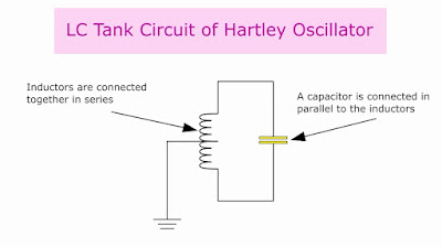
A Hartley oscillator is an electronic LC oscillator that consists of an amplifier and a feedback circuit whose frequency is determined by the LC tank circuit. It is also called the split inductance oscillator. This circuit was invented by Ralph Hartley in 1915. In this oscillator, the tuned circuit consists of a capacitor which is connected in parallel, with two inductors that are connected in series. The two inductors are connected together at the center as a center-tapped inductor.
Two Types of Hartley Oscillator
1. Series-fed Hartley oscillator: This is not commonly used because of its frequency instability.
2. Parallel or shunt-fed Hartley oscillator: This is highly stable and it is more commonly used.
Working of Hartley Oscillator
When a voltage VCC is applied, it crosses the radio frequency choke or RFC and increases the collector current. The RFC at the collector provides high reactance to higher frequencies and behaves as an open circuit. At DC voltages, it produces a low reactance condition and acts as a short circuit thus allowing the DC to pass through. The collector current signal reaches the tank circuit through the output coupling capacitor C2. It charges the capacitor C of the tank circuit and the energy is stored as an electrostatic field.
When the capacitor C is fully charged, it then goes into discharge and this discharge reaches the inductor L1. The L1 gets charged and the charge is stored as a magnetic field. When the L1 is fully charged, it then goes into discharge and this discharge returns back to the capacitor C and charges it. This back and forth charging and discharging goes on between the capacitor and the inductors which forms a sine wave. It changes its direction each time it charges and discharges. This sine wave is less intense and has a negative alternation.
The mutual induction between the L1 and L2 transfers energy from the collector circuit to the base of the transistor. The oscillations at the L1 are transferred to L2 and this causes a 180 degree phase shift. The energy from the tank circuit is fed directly to the base of the transistor through a coupling capacitor C1. The NPN transistor with a common emitter configuration amplifies the signal and inverts it into 180 degrees. The oscillations at the LC tank circuit and the output are in phase.
Hartley Oscillator Circuit
Advantages of the Hartley Oscillator
- The Hartley oscillator needs few components at the LC tank circuit.
- The amplitude of the signal is constant over a wide frequency range.
- The frequency may be varied by changing the value of the capacitor or the inductor.
Disadvantage of the Hartley oscillator
The sine-wave of the Hartley oscillator contains many harmonic components thus pure sine-wave cannot be obtained.
Calculation to find the Frequency of Oscillation of a Hartley Oscillator
The frequency of oscillation of the Hartley oscillator is calculated by the formula
F = 1/2π√LT C,
Where LT = L1 + L2 + 2M
2M is the mutual inductance between the two inductors
Applications of Hartley Oscillator
- It is used as a local oscillator in radio receivers.
- It is used in frequency converters and doublers.
Watch the Video: https://youtu.be/Xs3dd7gbZrI


No comments:
Post a Comment