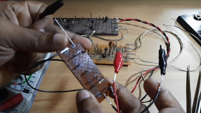
RF probe is an electronic test equipment which is used to measure the strength of radio frequency signals in an electronic circuit. The RF probe converts the high frequency RF signal of a testing circuit into a DC signal, which can be read and measured using a multimeter or an oscilloscope. It gives a relative reading of the RF amplitude. RF probe is used only in low power radio frequency signals. It is used at a frequency range of 100 kHz up to 3 GHz.
Uses of an RF Probe
This probe is used for testing and doing adjustments in oscillators, receivers, modulators, transmitters etc. It is used in radios for tuning IF stages, adjust filter responses, aligning the radio, peaking RF stages, examining the amplitude modulation etc.
This probe is used for testing and doing adjustments in oscillators, receivers, modulators, transmitters etc. It is used in radios for tuning IF stages, adjust filter responses, aligning the radio, peaking RF stages, examining the amplitude modulation etc.
Challenges for Measuring an RF signal
There are challenges in measuring an RF signal because of the high frequency involved, low power, the nature of the circuit to be measured such as an oscillator, that can overload when attaching a testing lead etc. In circuits where the loading of a section is critical, high impedance probes are used which extracts a very small amount of RF energy, amplifies it to a suitable level and converted into DC, which can be measured using a suitable test instrument.
RF Probe Circuit
The RF probe circuit consists of two diodes, two capacitors, a resistor and a variable resistance. Use of the germanium diode gives the best response to the circuit. A multimeter or an oscilloscope helps to measure the detected DC signal.
The RF probe circuit consists of two diodes, two capacitors, a resistor and a variable resistance. Use of the germanium diode gives the best response to the circuit. A multimeter or an oscilloscope helps to measure the detected DC signal.
1N64 Germanium Diode
Working of the Circuit
The input capacitor of the probe collects an RF sample of the circuit to be tested. When the voltage falls, it eventually turns on the first diode and builds up a voltage across the node. When the voltage rises up, it turns on the second diode charging the second capacitor. The capacitor charges close to the peak of the amplitude of the signal. A 10k resistor is used to release the charge from the capacitor. The rectified DC signal is allowed to pass through the circuit, which is read using a multimeter or an oscilloscope.
Measuring the signal output from a VFO
Watch the Video: https://youtu.be/DMF4Fp1xT0Q


No comments:
Post a Comment