A singly balanced diode ring product detector is a passive radio frequency mixer or product detector that does not need a supply voltage to operate. Here, two diodes are used along with a broadband transformer that utilizes trifilar windings over a ferrite balun core or toroid.
The diode ring mixers are broadband and operate on a wide range of frequencies. They have relatively lower noise figures as compared to the active mixers. These are also called as balanced mixer/product detectors because it prevents the local oscillator signal from appearing at the RF input or the audio output ports.
Diodes used in the product detector
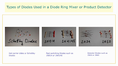
The diodes that are commonly used here are the hot-carrier diodes or Schottky diodes, although high-speed silicon switching diodes such as 1N4148 or 1N914 etc. are also used. Detector diodes like the 1N60 were used without much difference in performance. The forward voltage drop across each diode in the ring determines the mixer's drive level required for optimum performance.
The local oscillator signal must be around 20 dB higher than the RF signal for adequate operation. The characteristics of this product detector like the bandwidth or frequency response depends upon the winding of the transformer, such as the number of turns, distance between the turns, permeability of the core etc.
Winding the Broadband Transformer
The broadband transformer utilizes trifilar windings over a ferrite balun core or a toroid core. For high frequency spectrum, ferrite cores of high permeability such as Amidon type FT-37 to FT-43 cores are used.
A typical transformer consist of 10 turns trifilar windings of #28 or #30 SWG enameled copper wire is wound through a ferrite core or balun core. For VHF or UHF frequencies, cores with still lower permeability such as 125 material or Amidon type FT-61 are used. The local oscillator signal power of about +15 dBm is necessary for optimum performance of this product detector. An RF voltage measured at around 250-300 millivolts is needed to adequately run this mixer/product detector.
Working of the Circuit
The VFO signal is applied at point C, which is the intersection of the two secondary windings of the transformer and the radio frequency choke. A signal at point C drives the two secondary windings of the transformer in opposite directions. As the signal at point C swings to the positive side, the upper diode A conducts, which places a charge at the 0.01uF capacitor. On the negative swing of the signal at point C, the lower diode B conducts, which removes the charge from the capacitor. Therefore, the overall charge becomes zero.
However, when a carrier signal comes across the transformer from the RF input, one of the diodes conducts earlier or later. It causes an unbalance in the net current flow to the capacitor. This unbalance across the diodes causes a charge to be observed across the capacitor as an audio voltage, which is received at the output.
Circuit Description
This product detector has two input ports and an output port. One of the input ports is for the RF input from the antenna and the other for the local oscillator injection. The detected audio signal is obtained from the output port. The RF signal from the antenna is given at the center tap of the secondary winding of the transformer through a 0.01 uF capacitor. The center tap of the secondary winding is terminated by an RF choke towards the ground. The local oscillator signal is given at the primary winding of the transformer.
The output of the product detector is obtained from the junction point of the two diodes. A low pass audio filter is given to filter off the RF components from this audio signal. It is then amplified by an audio preamplifier to boost the weak signals before it is further amplified by a power amplifier and fed through the loudspeaker. The hum that is audible at the output can be reduced by attaching a balanced antenna at the input or by connecting about 10 meters of wire, with one end of the wire connected to the circuit ground and the other end spread across the ground.
Disadvantages of the Diode Product Detector
Disadvantages of the Diode Product Detector
- The singly balanced two diode product detectors have an insertion loss of about 5db.
- It needs a higher local oscillator drive signal than the active detector, and needs a local oscillator drive of +15dBm.
- An audio preamplifier stage is necessary to sufficiently amplify the weak audio signals.


No comments:
Post a Comment